功能 #2545
已关闭功能 #2519: Ford_SYSR: System Requirement
Ford_SYSR:FS_REQ0025_V3 Turn Indicator Feedback
100%
描述
Under normal operating conditions, the LDM shall report Turn indicator status to the BCM by outputting the received signal from the BCM over the ‘L/RF_LED_Turn_Outage_Ckt’ line. The feedback must be stable 70ms after BCM output Turn on. The BCM does a 50 ms (max) debounce. The BCM makes the decision 120 ms (70 + 50) after Turn on.
TI outage detection report shall also occur via a hard wire back to BCM. Feedback signal will follow the “on/off” pattern matching the input signal from turn indicator input when no outage is detected. In case of outage Signal will remain “LOW” status the whole time.
• No Outage: Signal goes "HIGH” when TURN LEDs are activated.
• Outage: Signal remains "LOW" when TURN LEDs are activated.
• Outage: Signal remains continuous “High” when TI is activated and TI input short to Battery.
Note: BCM uses an active high input which has a 1.3K Ohm pull down resistor. The LDM module shall implement a high side driver with built-in short to ground protection circuit for outage feedback.
Following BCM TI outage feedback input max values to be considered:
Input Voltage Range: 8 – 19 V
Input Current Range: 0.007- 0.015 A
If no TI outage detected, the feedback should be equal or more than 8V(Shall consider to meet the requirement while 9-16V power supply);
If any TI outage detected, the feedback should be less than 2V.

Figure 8: Turn Indicator Feedback Description
文件
由 玉洁 金 更新于 超过一年 之前
- 文件 clipboard-202411120933-ddnon.png clipboard-202411120933-ddnon.png 已添加
- 主题 从 Ford_SYSR:FS_REQ0025_V2 Turn Indicator Feedback 变更为 Ford_SYSR:FS_REQ0025_V3 Turn Indicator Feedback
- 描述 已更新。 (差异)
- 状态 从 新建 变更为 进行中
由 玉洁 金 更新于 大约一年 之前
Under normal operating conditions, the LDM shall report Turn indicator status to the BCM by outputting the received signal from the BCM over the ‘L/RF_LED_Turn_Outage_Ckt’ line. The feedback must be stable 70ms after BCM output Turn on. The BCM does a 50 ms (max) debounce. The BCM makes the decision 120 ms (70 + 50) after Turn on.
TI outage detection report shall also occur via a hard wire back to BCM. Feedback signal will follow the “on/off” pattern matching the input signal from turn indicator input when no outage is detected. In case of outage Signal will remain “LOW” status the whole time.
• No Outage: Signal goes "HIGH” when TURN LEDs are activated.
• Outage: Signal remains "LOW" when TURN LEDs are activated.
• Outage: Signal remains continuous “High” when TI is activated and TI input short to Battery.
Note: BCM uses an active high input which has a 1.3K Ohm pull down resistor. The LDM module shall implement a high side driver with built-in short to ground protection circuit for outage feedback.
Following BCM TI outage feedback input max values to be considered:
Input Voltage Range: 8 – 19 V
Input Current Range: 0.007- 0.015 A
If no TI outage detected, the feedback should be equal or more than 8V(Shall consider to meet the requirement while 9-16V power supply);
If any TI outage detected, the feedback should be less than 2V.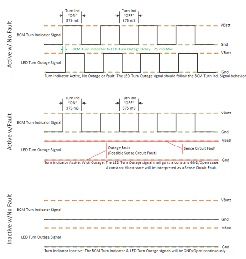
Figure 8: Turn Indicator Feedback Description